ADC
The goal here is to read analog data from a Java program running on a Raspberry PI.
For this example, we will be using a potentiometer like this one.
When the user turns the knob of the potentiometer, its resistance will vary, and the output current will go from 0 Volt (0%) to 3.3 Volts (100%).
We want to catch those numbers from a Java program running on a Raspberry PI.
If we can do that, we can easily replace the potentiometer with a thermometer, a photovoltaic cell, a pressure sensor, and earthquake detector..., whatever can send an analog signal.
| GPIO Interface | The cobbler | The ADC |
|---|---|---|
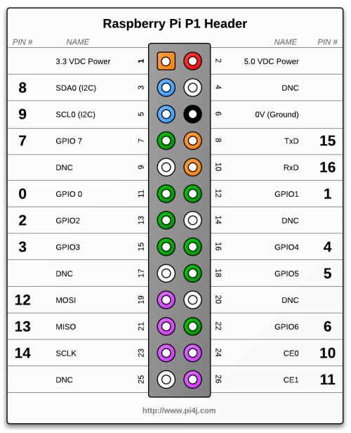 |
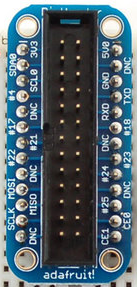 |
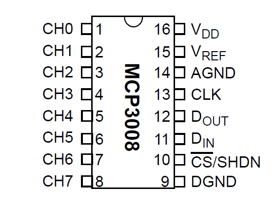 |
| Slice of PI | ||
 |
||
| GPIO | Cobbler | Slice of PI |
MCP3008 | Potentiometer | Color | |
|---|---|---|---|---|---|---|
| Pin # | Name | |||||
| 1 | 3.3 VDC | 3V3 | 3V3 RX |
VDD VREF |
right pin, #3 | red |
| 6 | 0V | GND | GND | AGND DGND |
left pin, #1 | black |
| 12 | GPOI1 | #18 | G18 | CLK | orange | |
| 16 | GPOI4 | #23 | G23 | DOUT | yellow | |
| 18 | GPOI5 | #24 | G24 | DIN | blue | |
| 22 | GPOI6 | #25 | G25 | CS | violet | |
| CH0 | middle pin, #2 | gray | ||||
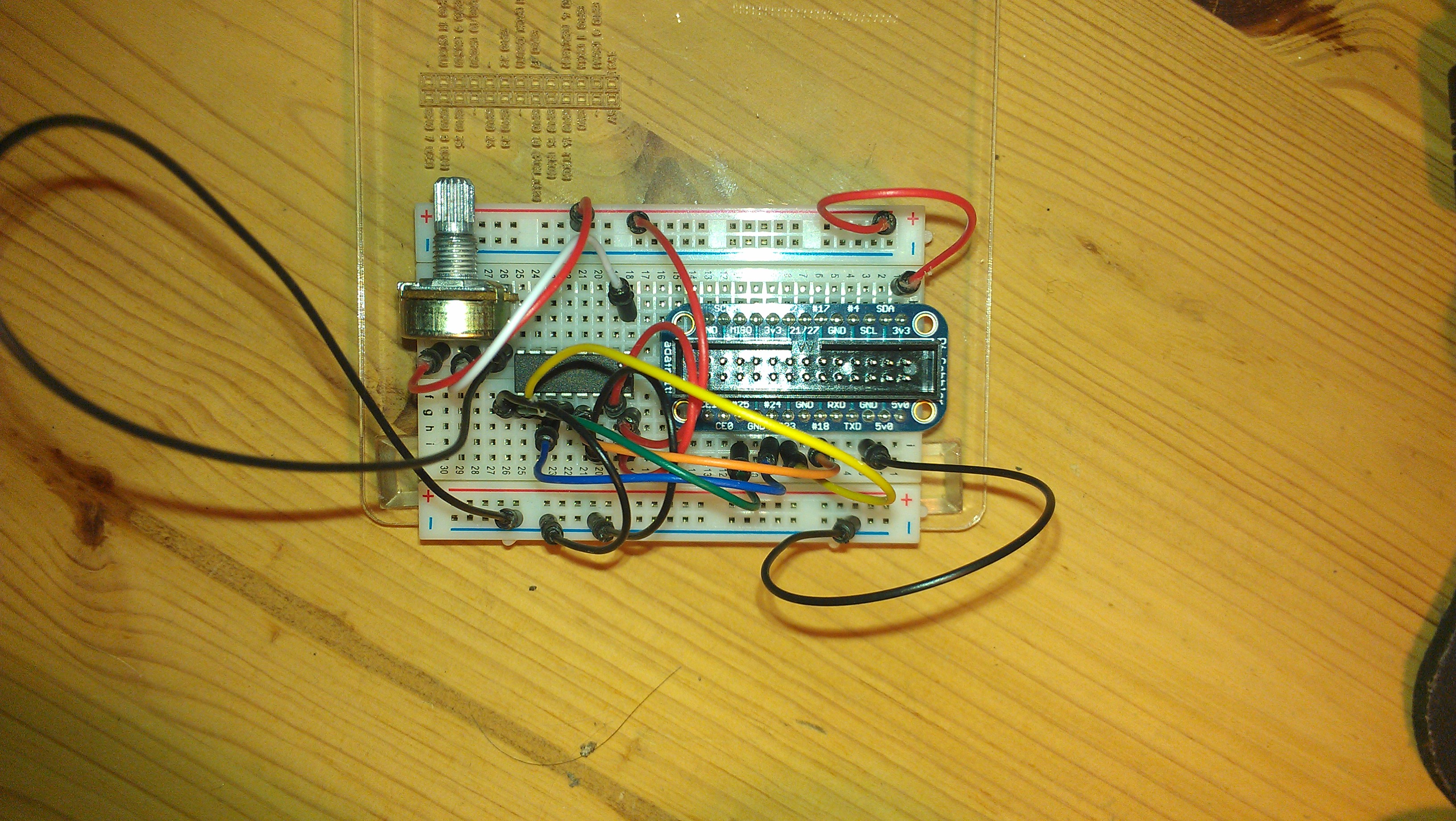
The breadboard, the cobbler and the ADC, wired, with the potentiometer.
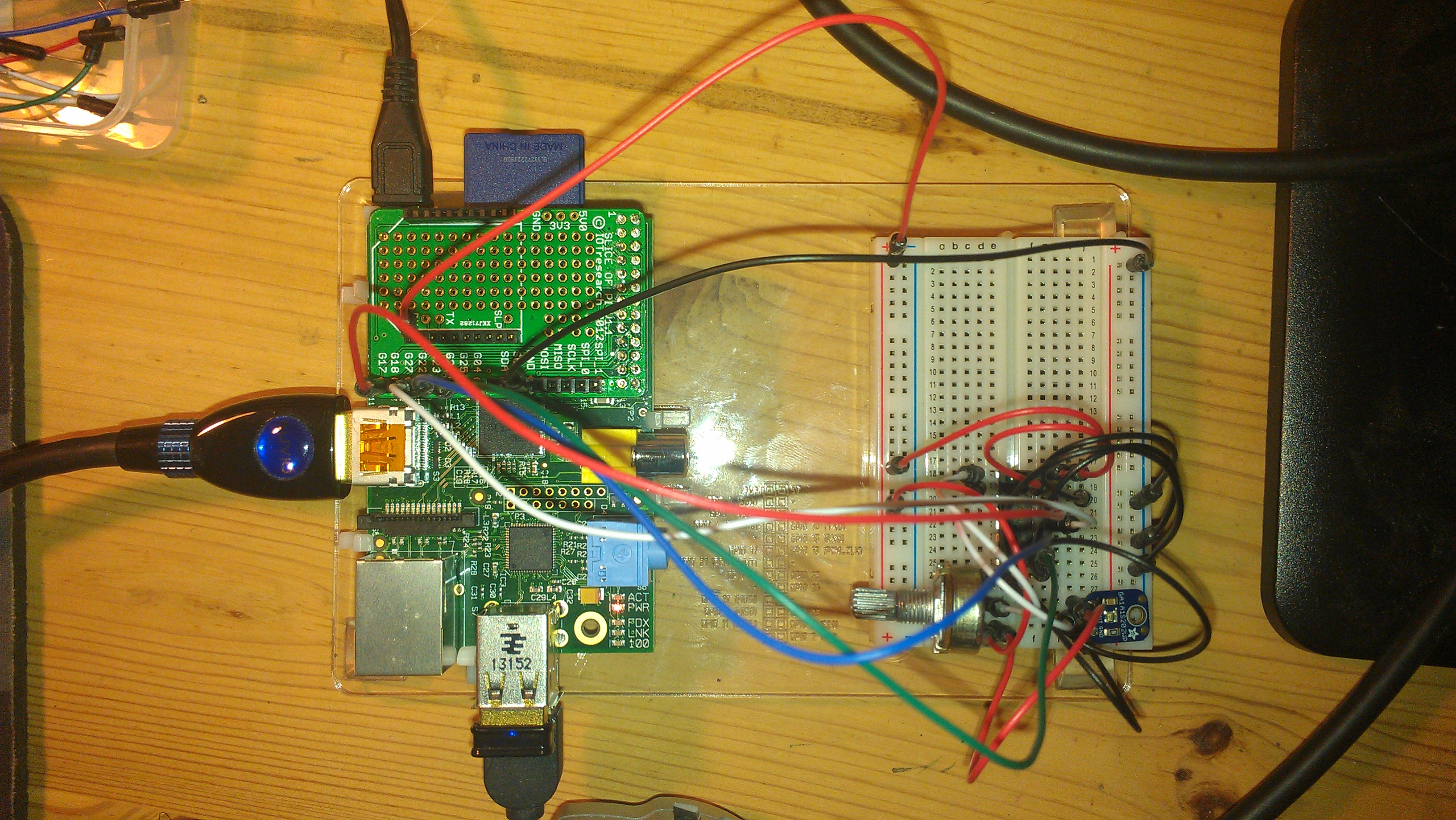
More room left on the breadboard.
The Raspberry PI will play the Master.
The MCP3008 will play the Slave.
Note: For clarity, we showcase here a simple, unique Java class. The code could be much better architected by implementing an Observer and a Listener. Such a code is also available, see in the repository the classes in the adc package, namely adc.ADCObserver, adc.ADCListener and adc.ADCContext. An example showing how to use them is featured in adc.sample.SampleMain.
readAdc(). It uses the pins mentioned earlier, identified with the classes and methods provided by PI4J.
    77    private static int readAdc()
    78    {
    79      chipSelectOutput.high();
    80
    81      clockOutput.low();
    82      chipSelectOutput.low();
    83
    84      int adccommand = ADC_CHANNEL;
    85      adccommand |= 0x18; // 0x18: 00011000
    86      adccommand <<= 3;
    87      // Send 5 bits: 8 - 3. 8 input channels on the MCP3008.
    88      for (int i=0; i<5; i++) //
    89      {
    90        if ((adccommand & 0x80) != 0x0) // 0x80 = 0&10000000
    91          mosiOutput.high();
    92        else
    93          mosiOutput.low();
    94        adccommand <<= 1;
    95        clockOutput.high();
    96        clockOutput.low();
    97      }
    98
    99      int adcOut = 0;
   100      for (int i=0; i<12; i++) // Read in one empty bit, one null bit and 10 ADC bits
   101      {
   102        clockOutput.high();
   103        clockOutput.low();
   104        adcOut <<= 1;
   105
   106        if (misoInput.isHigh())
   107        {
   108  //      System.out.println("    " + misoInput.getName() + " is high (i:" + i + ")");
   109          // Shift one bit on the adcOut
   110          adcOut |= 0x1;
   111        }
   112        if (DISPLAY_DIGIT)
   113          System.out.println("ADCOUT: 0x" + Integer.toString(adcOut, 16).toUpperCase() +
   114                                   ", 0&" + Integer.toString(adcOut, 2).toUpperCase());
   115      }
   116      chipSelectOutput.high();
   117
   118      adcOut >>= 1; // Drop first bit
   119      return adcOut;
   120    }
readAdc method are the ones we described in the MCP3008 section.
int, and returned to the caller.
readAdc() method is called in a loop from the main method. A SIGTERM (Ctrl+C) will terminate the program.
readAdc method is an int ranging from 0 to 1023, as we said before. This value is converted into a percentage (by dividing it by 10.23, which is 1023 / 100).
This value will be sent to the output (displayed) only if it is different from the previous reading.
ADCReader class:
     1  package analogdigitalconverter;
     2
     3  import com.pi4j.io.gpio.GpioController;
     4  import com.pi4j.io.gpio.GpioFactory;
     5  import com.pi4j.io.gpio.GpioPinDigitalInput;
     6  import com.pi4j.io.gpio.GpioPinDigitalOutput;
     7  import com.pi4j.io.gpio.Pin;
     8  import com.pi4j.io.gpio.PinState;
     9  import com.pi4j.io.gpio.RaspiPin;
    10
    11  /**
    12   * Read an Analog to Digital Converter
    13   */
    14  public class ADCReader
    15  {
    16    private final static boolean DISPLAY_DIGIT = false;
    17    private final static boolean DEBUG         = false;
    18    // Note: "Mismatch" 23-24. The wiring says DOUT->#23, DIN->#24
    19    // 23: DOUT on the ADC is IN on the GPIO. ADC:Slave, GPIO:Master
    20    // 24: DIN on the ADC, OUT on the GPIO. Same reason as above.
    21    // SPI: Serial Peripheral Interface
    22    private static Pin spiClk  = RaspiPin.GPIO_01; // Pin #18, clock
    23    private static Pin spiMiso = RaspiPin.GPIO_04; // Pin #23, data in.  MISO: Master In Slave Out
    24    private static Pin spiMosi = RaspiPin.GPIO_05; // Pin #24, data out. MOSI: Master Out Slave In
    25    private static Pin spiCs   = RaspiPin.GPIO_06; // Pin #25, Chip Select
    26
    27    private static int ADC_CHANNEL = 0; // Between 0 and 7, 8 channels on the MCP3008
    28
    29    private static GpioPinDigitalInput  misoInput        = null;
    30    private static GpioPinDigitalOutput mosiOutput       = null;
    31    private static GpioPinDigitalOutput clockOutput      = null;
    32    private static GpioPinDigitalOutput chipSelectOutput = null;
    33
    34    private static boolean go = true;
    35
    36    public static void main(String[] args)
    37    {
    38      GpioController gpio = GpioFactory.getInstance();
    39      mosiOutput       = gpio.provisionDigitalOutputPin(spiMosi, "MOSI", PinState.LOW);
    40      clockOutput      = gpio.provisionDigitalOutputPin(spiClk,  "CLK",  PinState.LOW);
    41      chipSelectOutput = gpio.provisionDigitalOutputPin(spiCs,   "CS",   PinState.LOW);
    42
    43      misoInput        = gpio.provisionDigitalInputPin(spiMiso, "MISO");
    44
    45      Runtime.getRuntime().addShutdownHook(new Thread()
    46                                           {
    47                                             public void run()
    48                                             {
    49                                               System.out.println("Shutting down.");
    50                                               go = false;
    51                                             }
    52                                           });
    53      int lastRead  = 0;
    54      int tolerance = 5;
    55      while (go)
    56      {
    57        boolean trimPotChanged = false;
    58        int adc = readAdc();
    59        int postAdjust = Math.abs(adc - lastRead);
    60        if (postAdjust > tolerance)
    61        {
    62          trimPotChanged = true;
    63          int volume = (int)(adc / 10.23); // [0, 1023] ~ [0x0000, 0x03FF] ~ [0&0, 0&1111111111]
    64          if (DEBUG)
    65            System.out.println("readAdc:" + Integer.toString(adc) +
    66                                            " (0x" + lpad(Integer.toString(adc, 16).toUpperCase(), "0", 2) +
    67                                            ", 0&" + lpad(Integer.toString(adc, 2), "0", 8) + ")");
    68          System.out.println("Volume:" + volume + "%");
    69          lastRead = adc;
    70        }
    71        try { Thread.sleep(100L); } catch (InterruptedException ie) { ie.printStackTrace(); }
    72      }
    73      System.out.println("Bye...");
    74      gpio.shutdown();
    75    }
    76
    77    private static int readAdc()
    78    {
    79      chipSelectOutput.high();
    80
    81      clockOutput.low();
    82      chipSelectOutput.low();
    83
    84      int adccommand = ADC_CHANNEL;
    85      adccommand |= 0x18; // 0x18: 00011000
    86      adccommand <<= 3;
    87      // Send 5 bits: 8 - 3. 8 input channels on the MCP3008.
    88      for (int i=0; i<5; i++) //
    89      {
    90        if ((adccommand & 0x80) != 0x0) // 0x80 = 0&10000000
    91          mosiOutput.high();
    92        else
    93          mosiOutput.low();
    94        adccommand <<= 1;
    95        clockOutput.high();
    96        clockOutput.low();
    97      }
    98
    99      int adcOut = 0;
   100      for (int i=0; i<12; i++) // Read in one empty bit, one null bit and 10 ADC bits
   101      {
   102        clockOutput.high();
   103        clockOutput.low();
   104        adcOut <<= 1;
   105
   106        if (misoInput.isHigh())
   107        {
   108  //      System.out.println("    " + misoInput.getName() + " is high (i:" + i + ")");
   109          // Shift one bit on the adcOut
   110          adcOut |= 0x1;
   111        }
   112        if (DISPLAY_DIGIT)
   113          System.out.println("ADCOUT: 0x" + Integer.toString(adcOut, 16).toUpperCase() +
   114                                   ", 0&" + Integer.toString(adcOut, 2).toUpperCase());
   115      }
   116      chipSelectOutput.high();
   117
   118      adcOut >>= 1; // Drop first bit
   119      return adcOut;
   120    }
   121
   122    private static String lpad(String str, String with, int len)
   123    {
   124      String s = str;
   125      while (s.length() < len)
   126        s = with + s;
   127      return s;
   128    }
   129  }
bash shell, run the following:
 Prompt> CP=./classes:/home/pi/pi4j/pi4j-distribution/target/distro-contents/lib/pi4j-core.jar
 Propmt> sudo java -cp $CP analogdigitalconverter.ADCReader
Then turn the knob of the potentiometer, back and forth.
 Volume:10%
 Volume:11%
 Volume:12%
 Volume:13%
 Volume:14%
 Volume:15%
 Volume:16%
 Volume:17%
 Volume:18%
 Volume:19%
...
That is so kewl!
Several channels (MCP3008 channels) can be listened to "simultaneously" (up to 8 on the MCP3008).
I did the test with with several photovoltaic cells, oriented in different directions (like centered, left, right, up, and down). It's quite easy to understand which one gets the most light.
Picture that: based on that data, you could very well trigger some servo that would appropriately orient a solar panel, so you re-fuel the batteries of the Raspberry PI.
There we go! Now we are self sufficient!
There is in the repository a class named adc.sample.FiveChannelListener, that demonstrates how to listen simultaneously to 5 channels,
and render them in "some" graphical way. There is a swing GUI, also checked in, but too demanding on the Raspberry PI.
The one we talk about is using escape sequences, just like 30+ years back... That was yesterday!

The setting, with the Slice of PI.
There is a class, named analogdigitalconverter.mcp3008.MCP3008Reader, easier to reuse.
See an example in analogdigitalconverter.mcp3008.sample.MainMCP3008Sample.